


 Top Rated Course

We may not have the course you’re looking for. If you enquire or give us a call on 01344203999 and speak to our training experts, we may still be able to help with your training requirements.
UML Class Diagram: A Comprehensive Exploration
Eliza Taylor 26 August 2024A UML Class Diagram serves as a blueprint for visualising and designing the software system structure. It shows what objects are involved and how they interact. Continue reading this blog to learn about the UML Class Diagram definition, its benefits, key components, and more. Let's embark on a new knowledge journey!

Training Outcomes Within Your Budget!
We ensure quality, budget-alignment, and timely delivery by our expert instructors.
Table of Contents

Are you an aspiring software engineer? Are your curious minds intrigued when you think about information technology? If so, your software engineering journey is incomplete without a UML Class Diagram! A UML Class Diagram is basically a type of diagram used in software engineering to illustrate a system's structure. It shows the system's classes, attributes, methods, and the relationships between the classes.
In this blog, we will explore all the related information (definition, benefits, etc,.) to help you navigate the realm of software engineering. Wasting no time, let's ramp up your curiosity!
Table of Contents
1) What is a Class Diagram in UML?
2) Benefits of Class Diagrams
3) Why Use a UML Class Diagram?
4) Basic Components of a Class Diagram
5) How to Draw Class Diagrams
6) Relationships Between Classes
7 Conclusion
What is a Class Diagram in UML?
A Class Diagram in Unified Modeling Language (UML) is a visual representation of the software system’s structure. It consists of the system’s class, attributes (data), methods (functions or behaviours), and the class relationship.
It forms the blueprint for the software engineers to understand the system’s structure and lays the foundation to design their components.
A UML Class Diagram helps software engineers plan and visualise how different software system parts, like a library, interact with each other. It is a kind of map that shows all the parts of the system and how they connect, making it easier for them to build and understand the system.
Let’s understand it with a real-life example of a Library Management System.
In a library, you have books, members, and librarians. Here's how a UML Class Diagram might look for this system:
|
Class: Book Attributes: title, author, ISBN, publishedDate Methods: borrow(), return(), reserve() Class: Member Attributes: memberId, name, email, membershipDate Methods: borrowBook(), returnBook(), reserveBook() Class: Librarian Attributes: librarianId, name, email, hireDate Methods: addBook(), removeBook(), manageMember() Relationships: Member borrows Book: The Member and Book classes are associated, indicating that members can borrow books. Librarian manages Book: There is an association between the Librarian and Book classes, indicating that librarians can add or remove books. Diagram: Book title: String author: String ISBN: String publishedDate: Date borrow(): void return(): void reserve(): void Member memberId: String name: String email: String membershipDate: Date borrowBook(): void returnBook(): void reserveBook(): void Librarian librarianId: String name: String email: String hireDate: Date addBook(): void removeBook(): void manageMember(): void Associations: Member -- borrows -- Book Librarian -- manages – Book |
This UML Class Diagram helps to visually represent the entities in the library management system and their interactions, making it easier to understand and design the system.

Benefits of Class Diagrams
UML Class Diagrams incorporate several benefits. These benefits are described below:
a) Modelling Class Structure: Class diagrams represent classes and their attributes, methods, and relationships, providing a clear and organised view of the system's architecture.
b) Identifying Abstractions and Encapsulation: They encourage the identification of abstractions and the encapsulation of data. This supports object-oriented design principles, such as modularity and information hiding.
c) Blueprint for Implementation: They guide developers in writing hassle-free codes by depicting the classes, attributes, methods, and relationships. This ensures consistency throughout the process.
d) Understanding Relationships: These diagrams depict relationships between classes, which helps stakeholders understand how different system components are connected.
e) Communication: They provide visual and standardised representations that both technical and non-technical audiences can seamlessly understand.
f) Code Generation: Developers can quickly generate a significant portion of codes from a visual representation. This decreases the chances of manual errors and saves valuable time.
Design and analyse Software Systems with Analysis & Design using UML Training- sign up now!
Why Use a UML Class Diagram?
UML Class Diagrams are essential tools in Software Engineering for several reasons.
Firstly, they help model a system's class structure by representing classes and their attributes, methods, and relationships. This provides a clear and organised view of the system’s architecture, making it easier to understand and communicate the design.
Secondly, they help facilitate understanding relationships between different parts of the system. These UML Class Diagrams depict associations, aggregations, compositions, inheritance, and dependencies, assisting stakeholders in knowing how various system components are connected.
Thirdly, they provide a visual and standardised representation that can be easily inferred by both technical and non-technical audiences, bridging the gap between different perspectives.
Another reason to use UML Diagrams is code generation. Some software development tools support generating code directly from class diagrams, which significantly reduces manual errors and saves valuable development time.
Basic Components of a Class Diagram
There are three components of the UML Diagram. These are listed below:
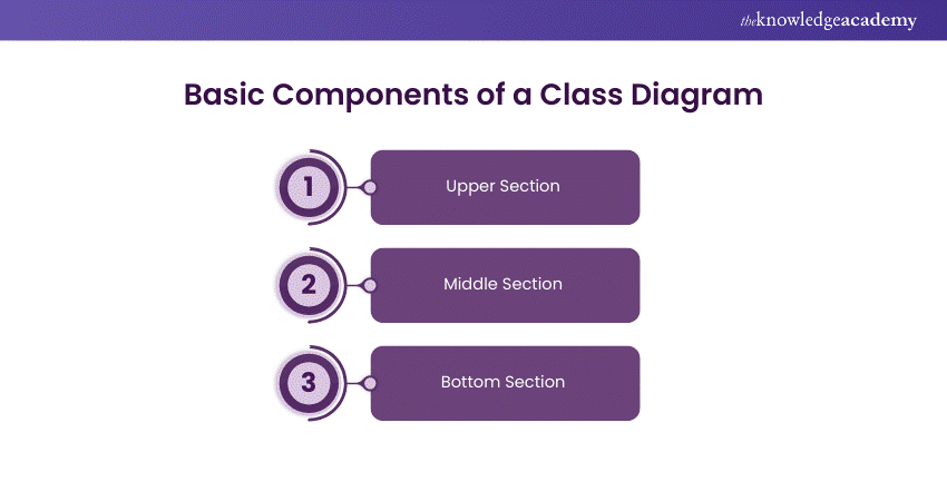
Upper Section
The upper section contains the class name, which is essential in both classifier and object contexts. This section identifies and distinguishes the class from others within the system. The reason it is listed as the 'upper section' is that the class name is always required. This provides a clear and straightforward way to reference the class within the diagram and in discussions about the system.
Middle Section
The middle section lists the class's attributes. These attributes describe the properties and qualities of the class, such as data fields or characteristics that instances of the class will have. This section is critical to convey a class's specific attributes, helping to outline the data structure each class instance will hold.
Bottom Section
The bottom section includes the class operations or methods, presented in a list format where each operation occupies its own line. These operations specify how the class interacts with data and performs its functions. This section is critical for understanding the operations that class instances can perform and how the class interacts with the rest of the system.
Upgrade your System Engineering skills with Our System Engineering Training- join now!
How to Draw Class Diagrams
1) Identify the Classes:
Identify your system's main components or objects (e.g., tables, records, queries) in a database system.
2) Draw Boxes for Each Class:
For each class, draw a box divided into three sections: the top for the class name, the middle for attributes, and the bottom for methods.
3) Name the Classes:
Write each class's name in the top section of each box (e.g., Tables, Records, Queries).
4) List Attributes:
In the middle section, list each class's attributes (properties or data) (e.g., for Table: tableName, numberOfColumns).
5) List Methods:
In the bottom section, list the methods (functions or behaviours) of each class (e.g., for Table: addRow(), deleteRow()).
6) Draw Relationships:
Draw lines between classes to show relationships. Use different types of lines to represent different relationships:
Association: A simple line showing that two classes are related (e.g., Table and Record). Inheritance: A line with a triangle arrow showing that one class inherits from another (e.g., User inherits from Person).
Aggregation/Composition: A line with a diamond showing a whole-part relationship (e.g., Database contains Tables).
7) Label Relationships:
Add labels to the lines to describe the relationships (e.g., "borrows" between Member and Book).
Relationships Between Classes
There are several types of relationships in object-oriented modelling , each serving a specific purpose. Here are some common types of relationships in class diagrams:
1) Association
An association represents a bidirectional relationship between two classes. It indicates that instances of one class are connected to cases of another class.
Diagram Representation: A solid line connecting the classes, with optional arrows indicating the direction of the relationship.
Example: In a database system, a Table contains multiple Records, each belonging to a specific Table. The Table class includes a reference to numerous instances of the Record class, representing an association.
2) Directed Association
A directed association represents a relationship between two classes where the Association has a direction, indicating that one class is associated with another in a specific way.
Diagram Representation: An arrowhead is added to the association line to indicate the direction of the relationship.
Example: A query is executed on a specific Table in a database system. The directed association arrow points from the Query class to the Table class, indicating that a query targets a specific table.
3) Aggregation
An aggregation is a specialised form of Association that represents a "whole-part" relationship. It denotes a stronger relationship where one class (the whole) contains or is composed of another class (the part).
Diagram Representation: A diamond shape on the side of the whole class.
Example: A database system contains multiple tables. The Tables are part of the Database, but if the Database ceases to exist, the Tables can still exist independently.
4) Composition
Composition is a stronger form of aggregation, indicating a more significant ownership or dependency relationship. In composition, the part class cannot exist independently of the whole class.
Diagram Representation: A filled diamond shape on the side of the whole class.
Example: In a database system, an Index is a part of a Table. If the Table is deleted, all associated Indexes are also removed, indicating that Indexes cannot exist without the Table.
5) Generalisation (Inheritance)
Inheritance represents an "is-a" relationship between classes, where one class (the subclass or child) inherits the properties and behaviours of another class (the superclass or parent).
Diagram Representation: A solid line with a closed, hollow arrowhead pointing from the subclass to the superclass.
Example: In a database system, the base class Query can have specialised subclasses like SelectQuery, InsertQuery, and UpdateQuery, each inheriting properties and behaviours from the Query class.
6) Realisation (Interface Implementation)
Realisation indicates that a class implements the features of an interface. It is often used when a class realises the operations defined by an interface.
Diagram Representation: A dashed line with an open arrowhead pointing from the incorporating class to the interface.
Example: Both the Table and View classes can implement a DatabaseObject interface in a database system. This interface includes methods like create(), read(), update(), and delete().
7) Dependency Relationship
A dependency exists between two classes when one class relies on another, but the relationship is not as strong as Association or inheritance. It represents a more loosely coupled connection between classes.
Diagram Representation: A dashed arrow.
Example: In a database system, a Report depends on a Query to fetch data. The Report class depends on the Query class to access and retrieve the necessary data for generating the report.
Build scalable Software Solutions with our Design and Architecture Training- join today!
Conclusion
UML Class Diagrams are indispensable tools in Software Engineering. They offer a visual and organised way to understand and design system structures. They assist in the visual representation of a system's classes, attributes, methods, and relationships, making design communication and consistency easier. Software engineers can use class diagrams to effectively model, implement, and maintain complex systems, thereby enhancing their comprehension and efficiency during the development process.
Transform your Software Development Process with Software Development Lifecycle Training – join today!
Frequently Asked Questions
What Are the Rules in UML Diagrams?

UML diagrams must follow standardised notation, accurately represent system components and their interactions, and use clear and consistent naming conventions. They must also correctly depict relationships such as associations, inheritance, and dependencies.
What are the Four Things That a Well-structured Class Diagram Should Have?
A well-structured class diagram should include classes with clearly defined names, attributes, and methods. It must also accurately represent relationships such as associations, aggregations, compositions, and inheritance between the classes.
What are the Other Resources and Offers Provided by The Knowledge Academy?
The Knowledge Academy takes global learning to new heights, offering over 30,000 online courses across 490+ locations in 220 countries. This expansive reach ensures accessibility and convenience for learners worldwide.
Alongside our diverse Online Course Catalogue, encompassing 17 major categories, we go the extra mile by providing a plethora of free educational Online Resources like News updates, Blogs, videos, webinars, and interview questions. Tailoring learning experiences further, professionals can maximise value with customisable Course Bundles of TKA.
What is The Knowledge Pass, and How Does it Work?
The Knowledge Academy’s Knowledge Pass, a prepaid voucher, adds another layer of flexibility, allowing course bookings over a 12-month period. Join us on a journey where education knows no bounds.
What are the Related Courses and Blogs Provided by The Knowledge Academy?
The Knowledge Academy offers various UML Courses including the introduction to UML and Analysis and Design using UML, among others. These courses cater to different skill levels, providing comprehensive insights into the Top 18 UML Diagram Tools.
Our Programming & DevOps Blogs cover a range of topics related to UML, offering valuable resources, best practices, and industry insights. Whether you are a beginner or looking to advance your knowledge of Data Analytics, The Knowledge Academy's diverse courses and informative blogs have got you covered.
Upcoming Programming & DevOps Resources Batches & Dates
Date
 Introduction to UML
Introduction to UML
Fri 15th Nov 2024
Introduction to UML
Fri 14th Feb 2025
Introduction to UML
Fri 11th Apr 2025
Introduction to UML
Fri 13th Jun 2025
Introduction to UML
Fri 15th Aug 2025
Introduction to UML
Fri 10th Oct 2025
Introduction to UML
Fri 12th Dec 2025
 If you wish to make any changes to your course, please


