We may not have the course you’re looking for. If you enquire or give us a call on +357 26030221 and speak to our training experts, we may still be able to help with your training requirements.
Training Outcomes Within Your Budget!
We ensure quality, budget-alignment, and timely delivery by our expert instructors.

Are you finding a better way to visualise complex software systems? Then try Unified Modelling Language (UML) Diagrams. UML simplifies intricate software design to provide a standardised view of software systems. It does this through diverse diagrams like Use Case Diagrams, Class Diagrams, and many more. Also, it fills the gap between the technical and non-technical stakeholders.
In this blog, we will explore the Unified Modelling Language (UML) and how it streamlines project workflows to create documentation. Explore this indispensable tool to enhance your understanding of modern engineering.
Table of Contents
1) What is UML?
2) The History of UML
3) The Importance of UML
4) Different Types of UML Diagrams
5) How to Create a UML Diagrams
6) Best Practices for UML Diagrams
7) The Benefits of Using UML Diagrams
8) Conclusion
What is UML?
UML is a standardised visual language designed to simplify the design and documentation of complex software systems. Developed in the 1990s, UML aimed to unify the various object-oriented modelling approaches used at the time. It serves as a blueprint for representing system architecture, design, and functionality, making it an essential tool in software engineering and other fields.
UML is a standardised framework used in software engineering to create visual representations of a system's design and structure. It includes a variety of diagrams, such as class diagrams, use case diagrams, and sequence diagrams, that help to model different aspects of a system. Class diagrams illustrate the system’s static structure by showing classes and their relationships, while use case diagrams depict functional requirements and interactions between users and the system. Sequence diagrams capture the dynamic flow of interactions, and activity diagrams represent workflows and processes.
By providing a common set of notations and methodologies, UML facilitates clear communication among stakeholders, including developers, designers, and project managers. It helps in visualising complex systems, ensuring that everyone involved has a shared understanding of the system’s architecture and behaviour. This clarity aids in the efficient development, maintenance, and documentation of software systems, making UML an essential tool in modern software engineering
The History of UML
The Unified Modelling Language (UML) has become a crucial tool in software engineering, providing a standardised framework for modelling complex systems. Its development in the 1990s unified various object-oriented Modelling methods into a single, cohesive language. Here is an overview of the key milestones in UML's evolution:
Creation of UML
The Unified Modelling Language (UML) was developed in the 1990s to unify various object-oriented Modelling methods.
Created by Grady Booch, James Rumbaugh, and Ivar Jacobson to establish a standard language for designing software.
Adopted by the Object Management Group (OMG) in 1997 as a global benchmark for software Modelling.
Early Development
In 1996, the OMG issued the first Request for Proposal (RFP), leading to a collaborative response from multiple organisations.
Rational Software formed the UML Partners alliance, which included organisations like Digital Equipment Corp, HP, IBM, Microsoft, Oracle, and others.
UML 1.0
UML 1.0 was developed and presented to the OMG in January 1997.
IBM, ObjecTime, Platinum Technology, and other companies submitted individual RFP responses during this period.
Refinement and UML 1.1
The UML Partners refined the initial proposal, resulting in UML 1.1.
UML 1.1 aimed to improve clarity and incorporate feedback from new collaborators.
Adoption and Evolution
The OMG adopted UML 1.1 in autumn 1997.
UML continued to evolve, progressing from UML 1.5 to UML 2.1.
The current version is UML 2.5.
The Importance of UML
UML is vital in contemporary software development as it offers a precise system architecture and design plan. UML diagrams enable the representation of intricate systems, enhancing their accessibility and comprehension. This clear visualisation greatly minimises confusion and mistakes in the development process, guaranteeing a more seamless project implementation.
Furthermore, UML encourages better collaboration and planning by improving team and stakeholder communication. It acts as a link between people with technical and non-technical backgrounds. Thus, aiding in conveying necessary needs, features, and procedures to business professionals who may lack coding knowledge.
UML helps teams save significant time and resources during the development lifecycle by enabling certain processes, such as visualisations of processes, user interactions, and the system's static structure.
Advance your career and become a tech leader with our comprehensive Software Engineering Courses today!
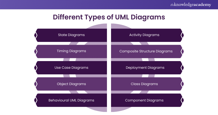
Different Types of UML Diagrams
UML employ certain elements to create UML diagrams. The diagram represents both static and dynamic parts of the system. Let’s explore it in detail:

1) State Diagrams
State Diagrams showcase the states of objects and how they respond to external events. They are useful when modelling dynamic system behaviour and impact objects' life cycles.
2) Timing Diagrams
Timing Diagrams emphasise the timing sequence of messages between objects. They display how objects interact over a specific period. These diagrams are helpful as they offer real-time data.
3) Use Case Diagrams
The UML Use Case Diagram assess the engagement between the system and the users. They tell the functionalities of the system from a distinct perspective. It also identifies user requirements along with the system boundaries.
4) Object Diagrams
Object Diagrams offer a snapshot of the system at a given time. They represent the relationship between objects and can visualise object structures well.
5) Behavioural UML Diagrams
Behavioural UML Diagrams focus on system dynamics. It illustrates how the system behaves and engages over time. Some examples of this include communication diagrams and sequence diagrams.
6) Activity Diagrams
Activity diagrams depict the sequence of actions in a system, including the order of steps and key decision moments. They are beneficial for illustrating business processes and workflows, offering a transparent display of simultaneous procedures and choice routes.
7) Composite Structure Diagrams
Diagrams of composite structures show a class's internal composition and illustrate its interactions among components. These visual representations are helpful in comprehending intricate internal formations and telling the relationships and partnerships among various class segments.
8) Deployment Diagrams
Deployment diagrams show how system components are physically deployed. They display physical nodes and software parts and how they are interconnected. Deployment diagrams play a vital role in strategising a system's infrastructure. They help visualise how software components are physically distributed and deployed.
9) Class Diagrams
Class diagrams are frequently utilised UML diagrams. A UML Class Diagram depicts the fixed formation of a system and display classes, attributes, operations, and associations. Class diagrams are essential for establishing the system's framework, outlining the classes and how they interact with each other.
10) Component Diagrams
Component diagrams represent the tangible parts of systems. They show software parts and how they are connected. Component diagrams are effective for illustrating a system's modularity and structure. They summarise the system's structure, displaying the parts and their connections.
How to Create a UML Diagram?
Let’s see how you can create a UML Diagram systematically. Just follow the instructions below steps:
1) Identify the Reason: Figure out the purpose of creating the UML diagram. Different UML diagrams fulfil various purposes, such as capturing requirements, designing system architecture, or documenting class relationships.
2) Recognise Elements and Relationships: Recognise the essential elements (like classes, objects, and use cases) and how they are related, which should be portrayed in the diagram. This stage requires comprehending the configuration and actions of the system being represented.
3) Select UML Diagram Type: Choose the UML diagram type most suitable for your modelling requirements. Typical examples include Class Diagrams, Use Case Diagrams, Sequence Diagrams, and Activity Diagrams.
4) Create a Rough Sketch: Make a rough drawing on paper or a whiteboard before using a UML modelling tool. This assists in visualising the arrangement and relationships among components.
5) Choose a UML Modelling Tool: Select a UML modelling tool that aligns with your preferences and needs. Different online and offline tools are accessible and have functionalities for making and adjusting UML diagrams.
6) Generate the Chart: Access the preferred UML modelling software and start a new project or diagram. Include components (such as classes, scenarios, and performers) in the chart and link them with the correct connections (like associations and dependencies).
7) Define Element Properties: Specify properties and attributes for each element in the diagram, including class attributes, methods, use case details, and any other diagram-specific information.
8) Add Annotations and Comments: Include annotations, comments, and explanatory notes to improve the clarity of your diagram. This will assist reviewers in comprehending the design choices and reasoning behind the diagram.
9) Verify and Assess: Evaluate the diagram to ensure it is precise and comprehensive, confirming that the connections, limitations, and components faithfully depict the desired system or process. Check your diagram for requirements and make any needed changes.
10) Improve and Revise: Modify the diagram following feedback and new insights. UML diagrams are frequently developed incrementally as the comprehension of the system progresses.
11) Create Documentation: Certain UML software permits direct documentation generation from diagrams, such as class documentation and use case descriptions.
Unlock the full potential of system development with our Analysis & Design Using UML Course—Sign up now!
Best Practices for UML Diagrams
UML is an effective instrument for displaying and recording system design. Following best practices is essential to produce impactful and meaningful UML diagrams. Below are a few important principles to follow:

1) Consider Your Audience: When developing UML diagrams, consider your audience. Adjust the depth of information and the selection of visuals to match the comprehension and requirements of your audience, whether they are developers, architects, or stakeholders.
2) Strive for Simplicity and Focus: When creating diagrams, strive for simplicity and focus. Every chart needs to highlight a distinct system element or a specific group of connections. Steer clear of clutter and extraneous details that may divert attention from the primary message.
3) Utilise Uniform Naming Conventions: Implement consistent and meaningful names for classes, objects, attributes, methods, and other UML elements. Precise and carefully planned naming conventions improve the comprehensibility of your diagrams.
4) Adhere to Standard UML Notations: When following UML guidelines, adhere to the standard UML notations and symbols. Using UML conventions consistently guarantees that people knowledgeable about UML can easily comprehend your diagrams.
5) Maintain Relationships Clearly: Clearly define and label connections between elements. Employ proper arrows, multiplicity notations, and association names to effectively convey the relationships between classes, objects, or use cases.
The Benefits of Using UML Diagrams
UML Diagrams provide various advantages, and that’s what makes it a remarkable tool. Let’s explore some of them here:

1) Standardisation: UML provides a uniform approach to displaying system models, enabling developers and stakeholders to communicate using a shared visual language.
2) Communication: UML diagrams effectively communicate with various stakeholders, such as developers, designers, testers, and business users. They make it easier to communicate complicated concepts and understandably.
3) Visualisation: UML diagrams facilitate the visualisation of system components, relationships, and processes, helping in understanding and designing complex systems.
4) Documentation: UML diagrams are helpful tools for documenting the structure and organisation of a system's architecture, design, and behaviour.
5) Analysis and Design: UML aids in both the analysis and design stages of software development. Its key function is to assist in shaping system requirements into a design ready for implementation.
Conclusion
In conclusion, we’ve thoroughly discussed the Unified Modelling Language (UML) in-depth. This standardised way of visualising system designs improves communication, understanding, and documentation. By incorporating it, developers can develop well-documented and robust software. However, the practices mentioned in this blog must be followed for clarity and effectiveness of UML Diagrams.
Start your journey and master the language of System Design with our Introduction to UML Training today!
Frequently Asked Questions

Some of the principles to be followed for Unified Modelling include clarity, simplicity, and consistency. Always use the notations and update the diagrams with stakeholders. This is to ensure relevancy and accuracy.

We use Unified Modelling Language to visualise, specify, document and design software systems. It enhances the understanding and communication in software development. It bridges the gap between the non-technical and technical stakeholders.

The main goal of UML is to offer a way to visualise system design. It does this by effective communication, understanding and documentation of complex systems. UML supports the application of design throughout the development process.

The Knowledge Academy takes global learning to new heights, offering over 30,000 online courses across 490+ locations in 220 countries. This expansive reach ensures accessibility and convenience for learners worldwide.
Alongside our diverse Online Course Catalogue, encompassing 17 major categories, we go the extra mile by providing a plethora of free educational Online Resources like News updates, Blogs, videos, webinars, and interview questions. Tailoring learning experiences further, professionals can maximise value with customisable Course Bundles of TKA.

The Knowledge Academy’s Knowledge Pass, a prepaid voucher, adds another layer of flexibility, allowing course bookings over a 12-month period. Join us on a journey where education knows no bounds.

The Knowledge Academy offers various UML Training, including the Introduction To UML, and Analysis & Design Using UML. These courses cater to different skill levels and provide comprehensive insights into Business Process Modelling Tools.
Our Programming & DevOps Blogs cover a range of topics related to Programming, offering valuable resources, best practices, and industry insights. Whether you are a beginner or looking to advance your Programming & DevOps Skills, The Knowledge Academy's diverse courses and informative blogs have got you covered.


 Top Rated Course


 If you wish to make any changes to your course, please


