We may not have the course you’re looking for. If you enquire or give us a call on +46 850282424 and speak to our training experts, we may still be able to help with your training requirements.
Training Outcomes Within Your Budget!
We ensure quality, budget-alignment, and timely delivery by our expert instructors.

Project Managers and IT professionals rely on the Network Diagram in Project Management. So, What is a Network Diagram? You ask. Network Diagrams are a powerful way of visualising how different devices and networks work together. They can also help you plan, troubleshoot, document, and communicate various aspects of a network.
A Network Diagram is a picture that shows how a computer or communications network is organised. In this blog, we will highlight what is a Network Diagram, the types and uses of Network Diagrams, and some tips and best practices for creating and using them.
Table of Contents
1) What is a Network Diagram?
2) Types of Network Diagrams
3) What is Network Topology and its examples?
4) Network Diagram Symbols
5) Conclusion
What is a Network Diagram?
Network diagrams, in essence, are graphic representations of networks and systems, serving the fundamental purpose of simplifying complexity. They play a pivotal role in a multitude of fields, offering a visual framework that simplifies the intricacies of network planning and management. Network Diagrams can be used for different purposes, such as the following:
1) Structuring office or house network
2) Understanding and troubleshooting any errors or bugs.
3) Update or upgrade an existing network
4) Documentation for communication, onboarding, planning, etc
5) Tracking, devices, components or jobs
6) Present process and steps to be taken while implementing a project

Types of Network Diagrams
Now that you know What is Network Diagram, let’s understand its types. These diagrams are of various types, each tailored to specific needs and objectives. Understanding these different types is essential for effectively conveying information and managing networks. Here are some of the most common types of Network Diagrams mentioned below:
Physical Network Diagram
A Physical Network Diagram shows the actual physical relationship between devices and components in the network. It can include details such as cables, ports, switches, routers, firewalls, servers, etc.
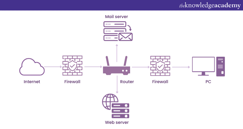
The above-shown Physical Network Diagram of a company network showcases the location and layout of the servers, routers, switches, firewalls, and other devices in different rooms and floors of the building. It also shows the type and length of the cables that connect the devices.
Logical Network Diagram
A Logical Network Diagram shows how the devices communicate and how information flows through the network. It can include subnets, network devices, routing protocols, IP addresses, etc.
Here is a Logical Network Diagram of the same company network. It shows the IP addresses and names of the servers, routers, switches, firewalls, and other devices and the subnets and VLANs they belong to. Coupled with that, a Logical Network Diagram also takes into account the usage of ports and their proper labelling. It also shows the routing protocols and security policies that are applied to the network.
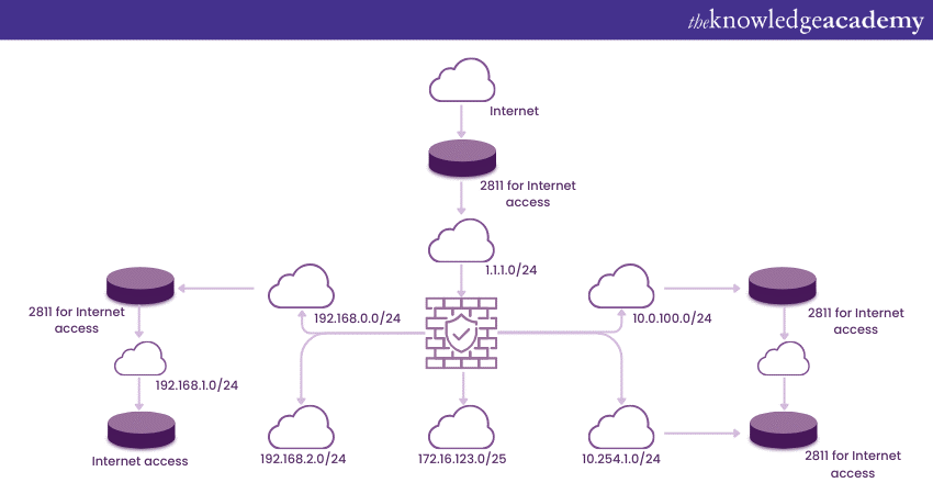
Here is a Logical Network Diagram of the same company network. It shows the IP addresses and names of the servers, routers, switches, firewalls, and other devices and the subnets and VLANs they belong to. Coupled with that, a logical Network Diagram also takes into account the usage of ports and their proper labelling. It also shows the routing protocols and security policies that are applied to the network.
You can see that the physical and logical Network Diagrams have different purposes and levels of detail. A physical Network Diagram can help plan and troubleshoot a network's installation and maintenance. A logical Network Diagram can help understand and optimise a network's performance and security.
Unlock your Project Management potential with the Project Management Black Belt Course – your path to mastery starts now!
What is Network Topology and its examples?
Network Topology is the layout or structure of a computer network, defining how devices are interconnected and how data flows between them. It encompasses various arrangements and configurations that determine the communication paths within a network, including physical and logical connections.
Understanding Network Topology is essential for designing, managing, and troubleshooting networks effectively, as it provides insights into network efficiency, scalability, and resilience. Here are some examples:
Bus topology
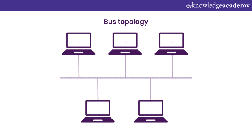
This diagram shows a network topology where a single cable or backbone connects all the nodes. The diagram represents the nodes, and a line represents the cable. The diagram also shows the terminators attached to both cable ends to prevent signal reflection.
Ring topology

This diagram shows a network topology where a circular cable or ring connects all the nodes. The diagram uses circles to represent the nodes and curved lines to represent the cable. The diagram also shows the direction of data transmission in the ring.
Star topology
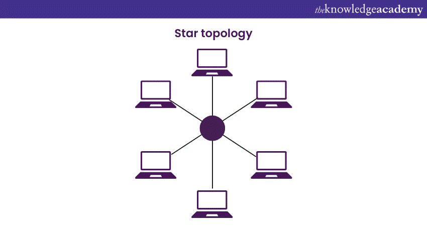
This diagram shows a network topology where all the nodes are connected to a central hub or switch. The diagram uses circles to represent the nodes and a star to represent the hub or switch. The diagram also shows the cables that connect the nodes to the hub or switch.
Mesh topology
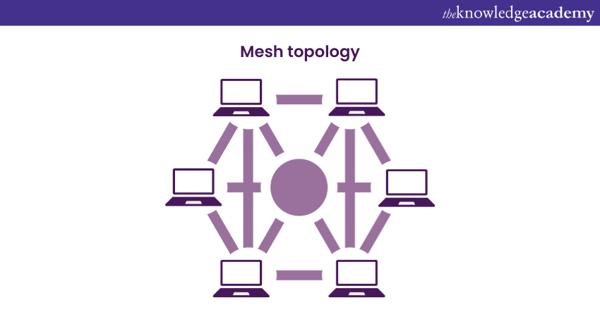
This diagram shows a network topology where all the nodes are connected directly or indirectly. The diagram uses circles to represent the nodes and lines to represent the connections. The diagram also shows the number of connections that each node has.
Unlock your potential with our Project Management Courses | Training & Certifications by taking the lead today!
Network Diagram symbols
Network Diagrams employ a specific set of symbols to convey information efficiently. These symbols act as a visual language, facilitating the understanding and communication of complex network structures. Understanding these symbols equips professionals with the ability to interpret complex Network Diagrams accurately.
Mastery of this visual language enhances communication, aids in troubleshooting, and enables effective collaboration among network administrators and stakeholders. Each symbol holds a unique meaning, aiding in the representation of various network components and their interactions.
a) Rectangles: Rectangles are often used to denote devices such as computers, servers, or routers. Their placement and connections in the diagram signify the physical or logical relationships between these devices.
b) Circles or ovals: These shapes typically represent endpoints in a network, such as computers, servers, or even network hubs. The use of circles helps distinguish endpoints from other components in the diagram.
c) Arrows: Arrows play a crucial role in indicating the flow of data or the direction of communication between different network elements. They showcase how information moves within the network, helping in the visualisation of data paths.
d) Lines and connectors: Lines connecting devices or symbols illustrate the connections between them. The style of the line – whether straight or curved – and its colour may convey additional information, such as the type of connection or the importance of the link.
e) Cloud symbols: Representing the internet or an external network, cloud symbols are commonly used to depict connections beyond the scope of the current diagram. This provides a clear demarcation between the local network and external elements.
f) Firewall icons: Firewalls are critical for network security. Specific symbols represent firewall devices, allowing network administrators to identify and analyse the placement and configuration of these security measures.
g) Switch symbols: Switches are integral components in local area networks (LANs). Network Diagrams use specific symbols to depict switches, showcasing their location and the devices connected to them.
h) Router icons: Routers link different networks and facilitate data transfer between them. Special symbols represent routers in Network Diagrams, emphasising their role in directing traffic between disparate networks.
Learn how to lead projects efficiently with our Introduction To Project Management Certification Course - start your journey to success today!
Conclusion
We hope that after reading this blog, you have understood What is Network Diagram. A Network Diagram is a useful tool for understanding and managing your network. It can help you with various tasks such as planning, troubleshooting, documenting, and communicating. By following the basics of Network Diagrams and the types and uses of Network Diagrams, you can create your own Network Diagram easily and effectively.
Unlock project success with our Software Estimation Training - Join now!
Frequently Asked Questions

Professionals rely on versatile software like Microsoft Visio or Lucidchart to create impactful Network Diagrams, offering intuitive interfaces and extensive libraries of Network symbols. Additionally, online platforms provide collaborative features, helping teams to work together seamlessly on diagramming projects.

Proficiency in Network Diagramming enhances problem-solving skills and facilitates clear communication within IT teams, positioning professionals for leadership roles. Moreover, mastery of Network Diagram tools showcases technical competence and adaptability, making individuals valuable assets in a rapidly evolving IT landscape.

The Knowledge Academy takes global learning to new heights, offering over 30,000 online courses across 490+ locations in 220 countries. This expansive reach ensures accessibility and convenience for learners worldwide.
Alongside our diverse Online Course Catalogue, encompassing 17 major categories, we go the extra mile by providing a plethora of free educational Online Resources like News updates, Blogs, videos, webinars, and interview questions. Tailoring learning experiences further, professionals can maximise value with customisable Course Bundles of TKA.

The Knowledge Academy’s Knowledge Pass, a prepaid voucher, adds another layer of flexibility, allowing course bookings over a 12-month period. Join us on a journey where education knows no bounds.

The Knowledge Academy offers Project Management Courses including Jira Masterclass, Software Estimation Training, and Smartsheet training. These courses cater to different skill levels, providing comprehensive insights into the Project controls.
Our Project Management Blogs covers a range of topics related to Project Management Businesses, offering valuable resources, best practices, and industry insights. Whether you are a beginner or looking to advance your Project Management skills, The Knowledge Academy's diverse courses and informative blogs have you covered.
Upcoming Project Management Resources Batches & Dates
Date
 Introduction to Project Management Course
Thu 1st Jan 1970


 Top Rated Course


 If you wish to make any changes to your course, please


